0
You have 0 items in your cart
- Home
- Tooling & Automation
- Companies & Capabilities
- Segen Quick Change
- News
- Resources
- About Us
- Contact Us
Our Majestic and Die Cad teams have deep experience in the engineering of new stamping dies for sheet metal applications. This experience and use of metal forming simulation software to determine part feasibility, material usage, potential part concessions, spring-back compensation, and tool processing requirements have earned us a reputation for designing dies for difficult parts with very little tryout time after the build.
Our knowledge of forming operations, material types, and part geometries allows us to achieve the best process, efficiency, and cost for each part, including those stamped from high-yield Dual Phase Steels, where we have years of proven experience.
Read our Die Design and Simulation article in Metalforming Magazine.
| CAD | CAM | SIMULATION | INSPECTION |
| AutoCAD | CATIA | AutoForm | Brown& Sharp PC-DMIS |
| AutoDesk | HyperMill | PAMStamp | Hexagon Data View & Page |
| CadKey | MasterCAM | MAGMA 5 (HPDC) | Polyworks |
| CATIA | PowerMill | Smit-ware | |
| IGESworks | Surfcam | Atos/GOM | |
| CREO | Work NC | ||
| SDRC | Tebis | ||
| SolidWorks | GibbsCAM | ||
| Unigraphics NX | |||
| VISI | |||
| Tebis | |||
| CapVidia |
Autoform
AutoForm is an intuitive, practical software solution for die-making and sheet metal forming. The specialized functions available with this software allow us to analyze, review and optimize functionality for forming processes up-front. With Autoform as part of our draw form simulation service, Die Cad Group is able to run practical tests for our customers without necessitating production of real product, saving them both time and money.
The Advantage
Designing to Exact Standards
Understanding the nuances behind the formability of a sheet metal part during the design phase results in a final design which is easy to produce. We have developed a reputation for being able to produce complex and advanced parts that meet the highest quality standards, every time. Our experienced Autoform simulation engineers help make sure that this remains a reality.
Providing Key Insights
Using Autoform, Tooling Tech Group can provide our customers:
CATIA V5
CATIA V5 boosts our capacity for innovation and helps to validate complexities that may arise during multiple stages of die design. Allowing us to quickly address the challenges of sheet metal components, this software helps make sure the end results align with our customer’s guidelines and meets exacting standards for efficiency and quality.
The Advantage
Designing to Exact Standards
Utilizing CATIA V5, we are able to provide 3D design, 2D layouts, surfacing and detailing services for your company. Our trained CATIA V5 Die Designers have the creative ability to visualize the process of manufacturing metal parts, the technical experience to read, analyze and interpret engineering drawings, and the needed expertise to determine the methodology to create a design to exacting standards.
Additionally, our transfer press simulation accepts CATIA V5 imports (among many other software formats). Tooling Tech Group’s transfer press simulation can provide key insights into your transfer die process before dies are machined, eliminating expensive and time-consuming fixes later in the build stage.
Pam Stamp
Pam Stamp virtual stamping software increases productivity and optimizes up-front engineering processes for more expediency towards creation of a tangible product. The ability to conceive everything virtually, from customer requests to ‘inspection’ of a final product, results in cost savings and elimination of waste product in final design.
The Advantage
Designing to Exact Standards
With Pam Stamp as part of our draw form simulation service, Die Cad Group is able to run practical tests for our clients without necessitating production of real product, reducing lead-times and development costs for our customers.
Understanding the nuances behind the formability of a sheet metal during the design phase results in a final design which is easy to produce. We have developed a reputation for being able to produce complex and advanced parts that meet the highest quality standards, every time. Our experienced Pam Stamp designers help make sure that this remains a reality.
Providing Key Insights
Using Pam Stamp, Tooling Tech Group can provide our customers:
Unigraphics (UG) NX
UG NX’s advanced CAD/CAM/CAE software is used throughout our tooling and die design processes. Utilizing Unigraphics (UG) NX lets us connect planning to production, providing a direct line for accurate machining data to your shop floor.
Connect Planning to Production
Designing to Exact Standards
UG NX is part of Tooling Tech Group’s 3D design, 2D layouts, surfacing and detailing network of software. Using UG NX as part of our surfacing and morphing services, we are able to more accurately and quickly produce a variety of part shapes, sizes, materials types and complexities. Our trained UG NX Die Designers have the creative ability to visualize the process of manufacturing metal parts, the technical experience to read, analyze and interpret engineering drawings, and the needed expertise to determine the methodology to create a design to exacting standards.
Providing Key Insights
Using UG NX, Tooling Tech Group can provide our customers:
Going beyond design, Majestic Industries is a single source for your stamping manufacturing needs. As specialists in the building of progressive and transfer dies, we are equipped to handle a single die project or a large program inclusive of multiple tools. With a well-stocked CNC machining department and excellent technicians, we can build dies ranging from 48 to 280 inches for forming materials such as mild steels (CR and HR), galvanized, stainless, HS and AHS steels, and aluminum.
We utilize the latest three-dimensional metrology solutions for dimensional analysis and quality control. Along with many years of high-strength material experience, using laser technology allows us to tackle very complex parts and get them dimensionally correct in a very expeditious manner. The all dies are verified by try-out on our own in-house presses.
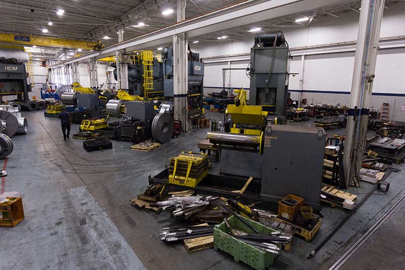
Majestic provides a full-service die repair and refurbishment department dedicated to around-the-clock emergency service. And, importantly, as part of these programs, we provide part bank runs to ensure you can keep your supply source up while your tool is being repaired. We handle all of the logistics, including picking up dies from your manufacturing plant and bringing them back to our facility for repair. To ensure we return the die to you with the highest precision and accuracy, we utilize the latest 3D metrology solutions for dimensional analysis and quality control with try-out runs on our in-house stamping presses.
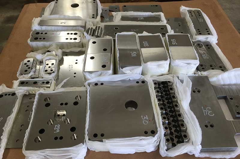
As vehicle program changes impact product design — whether for quality improvements, cost-savings efforts, safety fixes, or other reasons — we can modify the existing die sets to meet the new requirements.
If your part drawings do not exist, we can reverse engineer the dies using our laser scanning equipment to create a 3D model and quickly assess and update the die to accommodate the new design. As with any of our die designs, we then use advanced engineering and software tools to verify part feasibility and spring-back compensation.
The breadth of capability offered by our companies enables us to offer a variety of options for your tool design and build.
At Majestic, we can provide the highest quality dies at competitive rates. With our low-cost country die build programs, we design the dies here and then manage overseas manufacturing using best-cost suppliers. We receive fully machined and assembled dies verified through tryout and buy-off on our presses.
With Die Cad, we have a strategically located office in China staffed with in-country project managers. This allows us to oversee the quality and timing of offshore best-cost suppliers that manufacture and deliver fully machined, ready-to-assemble details for your tooling.
Prior to arrival on your shop floor, Die Cad unpacks the die components to clean and inspect each detail. We ensure all projects meet customer requirements and are ready to produce high-quality stampings.
At Majestic, we maintain a full stamping facility housing presses ranging in size from 800 to 2,750 tons that can handle low-volume runs of service parts, high-volume production or emergency offload for factory assist. We can handle dies from 48-in. to 280-in, coil stock up to 72″ wide and 50,000 lb., and material to 0.197″ thick.
All the presses feature tonnage monitors with the larger presses equipped with drop-through bolsters. The equipment can process a range of materials including CR steel, HR steel, galvanized, stainless, aluminum, and Advanced High Strength Steels (AHSS) including Dual Phase steels.
For production run parts In-die sensors and in-line camera vision systems provide real-time scanning for inspection of critical dimensions.
Additionally, we offer value-add assembly services, such as incorporating fasteners into the finished stamped part, as well as in-die and post-process staking and welding of nuts and studs.
| Bed Size | Shut Height | Coil Information | SPM | ||||||||||||||
| Press Make | Type (Prog / Transfer / Blanking / Tandem) | Max Tonnage | Scrap Shed (through bolster or shakers) | Front to Back (in) | Left to Right (in) | Window Size (in) | Min (in) | Max (in) | Stroke (in) | Max Coil Width (in) | Max Coil Thickness (in) | Max Coil Weight (lbs) | Coil ID (in) | Max Coil OD (in) | Minimum | Maximum | Other |
| Eagle | Prog/Transfer | 2750 tons | Drop thru Bolster | 108 | 280 | 108 | 48 | 60 | 36 | 72 | 0.38 | 50,000lbs | 20-24" | 70 | 10 | 22 | Puller |
| Eagle | Prog | 1200 tons | Drop thru Bolster | 108 | 216 | 74 | 33 | 44 | 16 | 72 | 0.25 | 30,000lbs | 20-24″ | 70 | 20 | 35 | Puller |
| Danly | Prog | 1500 tons | Drop thru Bolster | 96 | 188 | 74 | 38 | 48 | 16 | 72 | 0.25 | 30,000lbs | 20-24″ | 70 | 20 | 35 | |
| Heim | Prog | 800 tons | Shakers | 60 | 144 | 42 | 30 | 42 | 12 | 42 | 0.38 | 10,000lbs | 20-24″ | 60 | 15 | 35 | |
| Heim | Prog | 800 tons | Shakers | 70 | 144 | 53 | 31 | 42 | 12 | 52 | 0.38 | 20,000lbs | 20-24″ | 60 | 15 | 40 | |
Request a Quote

Proprietary Joining Solutions for Big Boy Toys
In this process, the heavy truck components (about 5-ft x 7-ft in size) are kept in a glue/bond apply station where a robot travels along a shuttle applying the adhesive to the different stations. The operator then manually loads the components in the front half of the cell and six components on the other side of the cell. The side with six components pivots up and is merged with the stationary side with the three components. The cycle then starts where cylinders are engaged to apply the pressure to finalize the bond
Combining Manual and Automated Processes
In this instance our customer asked us to develop a process to bond steel and composite brackets, apply glue and drill holes in a new 2.5 ft x 4 ft component in right-hand and left-hand styles.
In our process, the operator loads the component into the drill where six holes are drilled. The operator then takes the part and puts it into a loading nest where the robot picks up the part and moves it under a stationary dispensing head that applies the glue for the bracket reinforcements. While the glue is being applied, the operator is loading the brackets into the next station. Once these actions are completed, the robot then loads the part into the nest at the manual station and the assembly press closes automatically to complete the bonding process. A mix of two to three operators and one robot results in an efficient cycle time of 3 to 3.5 minutes
Confidential Design to Processing Multiple Part Styles
Our customer provided us the spec sheet outlining the time, temperature and recipe for a foam mix that needed to be applied in order to complete the manufacture of four different composite components.
We developed an automated dual line solution with two 6-axis robots and two shuttles functioning as axis 7 and 8 as the shuttle movements are interlocked with the robots. The operator loads the component on the fixture device and as the shuttle moves, the first robot arm is programmed to apply the foam. This robot then moves out of the way and the second robot moves in and measures the foam bead via a laser measuring system to ensure the right amount was applied. This robot then picks and place the component in the oven. Overall cycle time is 85.9 seconds.
From Four Machines to a Single Line
Our customer needed to produce two versions of a composite automotive part that required the routing of 100 holes and the application of 65 float nuts along with some rivet studs. In addition, they wanted a fully automated solution with +0.25mm tolerance on the holes, zero dust emission and a cycle time of just over three minutes. The customer thought it would take four machines to accomplish this.
Tooling Tech developed a solution that could route all the holes in a single orientation during a continuous process while using a minimum amount of floorspace. The process starts with the operator manually loading the part on a wall fixture where the automated cycle then starts. The part is clamped in place, the part style verified via a sensor, and several holes are drilled. The wall then rotates 180 degrees and a handling robot picks up the part and places it into the route cell where four robots cut about 65 holes. Each robot has a vacuum unit at its head and collects the dust during the routing process.
The handling robot then moves the part to the rivet nut station where two robots apply 66 float nuts, fed to the robots via a pneumatic tube. The nuts go in and are crimped using amperage as an indicator if the nut is properly secured. At the end of this process, all six robots communicate with the material handling robot to determine good or bad part.
Eliminating Human Error
We supplied our customer with a solution for welding two components together, where clinch nuts were already pressed in prior to welding. After welding, manual processes included the insertion of two push pins for a wiring harness operation and the application of a piece of double-sided tape. However, 10 – 15% of the components were being sent to quarantine due to missing parts.
Tooling Tech developed a fixturing station for assembly and a checking station to verify part presence. Once the part is welded, it is manually moved to the assembly station where the pin and tape are put in place. The part is then moved to the checking station where the part is clamped in place, and it goes through an automated checking cycle. Using a variety of sensors, the presence of the tape, clinch nuts and pins are all verified. This has saved the customer about $10,000/week.
In these days of lightweighting, it’s not only performance vehicles that benefit from composite structures. Introduced in 1987, the Jeep Wrangler has become an icon and popular across the world. With the 2018 model re-design, engineers were able to drop 200 pounds from the vehicle by employing aluminum bodywork and composite hardtop panels, with molds supplied by Tooling Tech Group. The frame is also 100 pounds lighter through extensive use of high strength steel.
Originally introduced in 2010, this performance truck shed 500 pounds in its 2017 iteration with a new aluminum body as well as composite hood and front fenders. This 2018 model has the same features, proving that lightweight materials can tough out off-road driving.
From the sleekest and sexiest of vehicles to the biggest boys on the highway, Tooling Tech Group provides molds for many heavy truck manufacturers. When you look at the size of these cabs, you can just imagine the weight reduction being achieved by the usage of composite materials.
This vehicle, commemorating the movie Bullitt starring Steve McQueen, was ‘the thing” at the 2018 Detroit Auto Show. To match the original movie car, this version is light on external badging and painted in the same dark green. However, the original was a steel vehicle and today’s version features composite panels.
Ford’s research into improved efficiency through weight reduction with advanced materials including new metals, alloys and composites began more than 25 years ago. Although the new 2019 Ranger features a high strength steel frame, the company is employing composite truck beds and body panels to help reduce vehicle weight. Other highlights include frame-mounted steel bumpers, an aluminum hood and tailgate, and standard automatic emergency braking and rearview camera.
Tooling Tech Group has long history of providing compression molds for various body panels on the Chevrolet Corvette, most recently providing the molds, bonding, drilling and assembly equipment for the C-7 and C-8 Stingray and Z06. The C6 Z06, introduced in 2006, was recognized for its use of advanced materials including an aluminum frame, magnesium roof structure, engine cradle and other suspension attachment points as well as light-weight, high-strength composite panels for the front fenders, front wheelhouses and rear fenders.