0
You have 0 items in your cart
- Home
- Tooling & Automation
- Companies & Capabilities
- Segen Quick Change
- News
- Resources
- About Us
- Contact Us
Majestic Industries can serve as a single source for your stamping die and production needs. Specializing in the design and build of progressive and transfer die tooling, we employ advanced processes to handle every step of the die build, from concept through finished product and die try-out on our selection of presses. We are also experts in designing dies to run mid-to-high-volume production of high-strength, dual-phase steel stampings.
With five state-of-the-art presses from 800 tons to 2,750 tons, Majestic is equipped to quickly step in and handle the stamping of production parts in a variety of materials in die sizes from 48” -280, plus we are certified to ship to any plant.
A simple phone call to the Majestic team will ensure your die gets repaired promptly. We arrange to truck your die to our facility, repair it, try it out on our stamping presses, and return it to you for production use, all in an extremely timely manner.
Majestic can help you get more life out of your stamping die with our refurbishment capabilities, which include die try-out to ensure accuracy. Plus, as part of our program management oversight, we make sure you have parts in the bank to use while your tool is being worked on.
Majestic offers you a one-stop shop for your stamping needs, helping to simplify your sourcing. We provide everything needed for die design, manufacture and repair, as well as being capable of handling your production stamping needs, including emergency work.
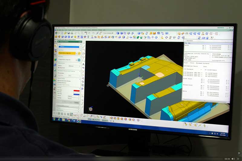
Majestic has a full engineering team to provide tool and die design, die details sourcing, product and process simulation, and other related services.
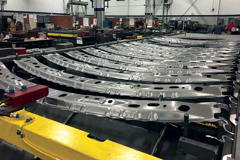
We have expertise in designing dies for stamping of advanced steel with higher strength and work-hardening tendencies during forming.
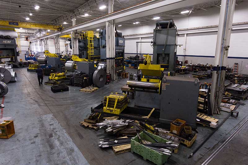
We have five stamping presses ranging in size from 800 tons to 2,750 tons ready to take on offload work.
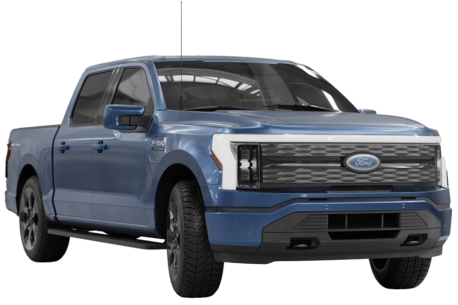
When it comes to automotive applications, Majestic’s capability encompasses building dies for every stamped structural component on a vehicle. That includes all powertrain and propulsion styles – internal combustion engine (ICE), electric vehicles (EV) and hydrogen fuel cells. Additionally, our services include secondary manufacturing services, such as incorporating fasteners into the finished stamped part, as well as in-die and post-process staking and welding of nuts and studs.

Majestic is experienced in design and build of stamping dies for a variety of structural parts used in the heavy truck industry – chassis, frame, suspension components, and more. Additionally, given our range of stamping presses, we can run production of large parts.

Majestic is ready for the growing use of alternative energy sources. We provide stamping dies for structural parts, such as racks, frames, and enclosures for the solar industry and energy storage. The quality of our tooling enables production of identical parts with minimal variation, leading to cost-effective manufacturing processes.
At Tooling Tech Group, our facilities are stocked with state-of-the art equipment run by highly skilled machine operators to ensure we deliver to you the highest quality molds, dies and fixtures.
Click on an item below to view details.
| Bed Size | Shut Height | Coil Information | SPM | ||||||||||||||
| Press Make | Type (Prog / Transfer / Blanking / Tandem) | Max Tonnage | Scrap Shed (through bolster or shakers) | Front to Back (in) | Left to Right (in) | Window Size (in) | Min (in) | Max (in) | Stroke (in) | Max Coil Width (in) | Max Coil Thickness (in) | Max Coil Weight (lbs) | Coil ID (in) | Max Coil OD (in) | Minimum | Maximum | Other |
| Eagle | Prog/Transfer | 2750 tons | Drop thru Bolster | 108 | 280 | 108 | 48 | 60 | 36 | 72 | 0.38 | 50,000lbs | 20-24" | 70 | 10 | 22 | Puller |
| Eagle | Prog | 1200 tons | Drop thru Bolster | 108 | 216 | 74 | 33 | 44 | 16 | 72 | 0.25 | 30,000lbs | 20-24″ | 70 | 20 | 35 | Puller |
| Danly | Prog | 1500 tons | Drop thru Bolster | 96 | 188 | 74 | 38 | 48 | 16 | 72 | 0.25 | 30,000lbs | 20-24″ | 70 | 20 | 35 | |
| Heim | Prog | 800 tons | Shakers | 60 | 144 | 42 | 30 | 42 | 12 | 42 | 0.38 | 10,000lbs | 20-24″ | 60 | 15 | 35 | |
| Heim | Prog | 800 tons | Shakers | 70 | 144 | 53 | 31 | 42 | 12 | 52 | 0.38 | 20,000lbs | 20-24″ | 60 | 15 | 40 | |
| Machines | Max Table Travel | Load LImit (lbs) | Controls | Machine Style |
|---|---|---|---|---|
| YCM DCV6030BF | 216 X 102 | 55115 | YCM FANUC | Bridgemill |
| Toshiba BP130.P40 | 160 X 90 | 55000 | Tosnuc 888 | Boring mill |
| Toshiba BTD 110.R16 | 78 X 64 | 13860 | Tosnuc 888 | Boring mill |
| Viper VMC1600 | 62 X 30 | Mitsubishi | Vertical spindle | |
| Okuma Howa Millac 852v | 80 X 32 | FANUC | Vertical spindle | |
| Okuma Howa Millac 852v | 80 X 32 | FANUC | Vertical spindle | |
| YCM WV108b | 42.6 X 29 | YCM FANUC | Vertical spindle | |
| OKK VM7-III | 60 X 29 | Mitsubishi | Vertical spindle | |
| Okuma Howa Millac 65v #11 | 51 X 15.6 | FANUC | Vertical spindle | |
| Makino a51nx | 25.2 X 11 | FANUC | Horizontal spindle | |
| Okuma Howa 561v w/ pallet changer | 41.3 X 22 | FANUC | Vertical spindle | |
| Kitamura 3XD | 30 X 20 | Mitsubishi | Horizontal spindle | |
| Kitamura 3XD | 30 X 20 | Mitsubishi | Horizontal spindle | |
| Kitamura 3XD | 30 X 20 | Mitsubishi | Horizontal spindle | |
| Viper VMC2000 GXT | 60 X 80 | 14000 | FANUC | Vertical spindle |
| Awea SP-3016 | 60 X 120 | FANUC | Vertical spindle | |
| Hyundai F500 | 20 X 40 | FANUC | Vertical spindle | |
| Hyundai F500 plus | 20 X 40 | FANUC | Vertical spindle | |
| Hyundai F400 | 18 X 30 | FANUC | Vertical spindle | |
| Hyundai F400 | 18 X 30 | FANUC | Vertical spindle | |
| Charmilles Rovofil 330 | 12 X 15.75 | Charmilles | Wireburn | |
| Charmilles Rovofil 330 | 12 X 15.75 | Charmilles | Wireburn | |
| Charmilles Rovofil 300 | 10 X 15.75 | Charmilles | Wireburn | |
| Mitsubishi M10049 | 13.75 X 19.7 | Mitsubishi | Wireburn | |
| Mitsubishi M10049 | 13.75 X 19.7 | Mitsubishi | Wireburn |
| Model | Table Size |
|---|---|
| Brown and Shape CMM | 35.5 x 47.25 x 35.5 |
| Mitutoyo KN-807 CMM | 27.5 x 33.5 x 24 |
| Leica Laser Scanner - at 960 T-Scan System |
Main Office:
15378 Hallmark Court
Macomb, Michigan 48042
Our Certifications Include:
Request a Quote

Proprietary Joining Solutions for Big Boy Toys
In this process, the heavy truck components (about 5-ft x 7-ft in size) are kept in a glue/bond apply station where a robot travels along a shuttle applying the adhesive to the different stations. The operator then manually loads the components in the front half of the cell and six components on the other side of the cell. The side with six components pivots up and is merged with the stationary side with the three components. The cycle then starts where cylinders are engaged to apply the pressure to finalize the bond
Combining Manual and Automated Processes
In this instance our customer asked us to develop a process to bond steel and composite brackets, apply glue and drill holes in a new 2.5 ft x 4 ft component in right-hand and left-hand styles.
In our process, the operator loads the component into the drill where six holes are drilled. The operator then takes the part and puts it into a loading nest where the robot picks up the part and moves it under a stationary dispensing head that applies the glue for the bracket reinforcements. While the glue is being applied, the operator is loading the brackets into the next station. Once these actions are completed, the robot then loads the part into the nest at the manual station and the assembly press closes automatically to complete the bonding process. A mix of two to three operators and one robot results in an efficient cycle time of 3 to 3.5 minutes
Confidential Design to Processing Multiple Part Styles
Our customer provided us the spec sheet outlining the time, temperature and recipe for a foam mix that needed to be applied in order to complete the manufacture of four different composite components.
We developed an automated dual line solution with two 6-axis robots and two shuttles functioning as axis 7 and 8 as the shuttle movements are interlocked with the robots. The operator loads the component on the fixture device and as the shuttle moves, the first robot arm is programmed to apply the foam. This robot then moves out of the way and the second robot moves in and measures the foam bead via a laser measuring system to ensure the right amount was applied. This robot then picks and place the component in the oven. Overall cycle time is 85.9 seconds.
From Four Machines to a Single Line
Our customer needed to produce two versions of a composite automotive part that required the routing of 100 holes and the application of 65 float nuts along with some rivet studs. In addition, they wanted a fully automated solution with +0.25mm tolerance on the holes, zero dust emission and a cycle time of just over three minutes. The customer thought it would take four machines to accomplish this.
Tooling Tech developed a solution that could route all the holes in a single orientation during a continuous process while using a minimum amount of floorspace. The process starts with the operator manually loading the part on a wall fixture where the automated cycle then starts. The part is clamped in place, the part style verified via a sensor, and several holes are drilled. The wall then rotates 180 degrees and a handling robot picks up the part and places it into the route cell where four robots cut about 65 holes. Each robot has a vacuum unit at its head and collects the dust during the routing process.
The handling robot then moves the part to the rivet nut station where two robots apply 66 float nuts, fed to the robots via a pneumatic tube. The nuts go in and are crimped using amperage as an indicator if the nut is properly secured. At the end of this process, all six robots communicate with the material handling robot to determine good or bad part.
Eliminating Human Error
We supplied our customer with a solution for welding two components together, where clinch nuts were already pressed in prior to welding. After welding, manual processes included the insertion of two push pins for a wiring harness operation and the application of a piece of double-sided tape. However, 10 – 15% of the components were being sent to quarantine due to missing parts.
Tooling Tech developed a fixturing station for assembly and a checking station to verify part presence. Once the part is welded, it is manually moved to the assembly station where the pin and tape are put in place. The part is then moved to the checking station where the part is clamped in place, and it goes through an automated checking cycle. Using a variety of sensors, the presence of the tape, clinch nuts and pins are all verified. This has saved the customer about $10,000/week.
In these days of lightweighting, it’s not only performance vehicles that benefit from composite structures. Introduced in 1987, the Jeep Wrangler has become an icon and popular across the world. With the 2018 model re-design, engineers were able to drop 200 pounds from the vehicle by employing aluminum bodywork and composite hardtop panels, with molds supplied by Tooling Tech Group. The frame is also 100 pounds lighter through extensive use of high strength steel.
Originally introduced in 2010, this performance truck shed 500 pounds in its 2017 iteration with a new aluminum body as well as composite hood and front fenders. This 2018 model has the same features, proving that lightweight materials can tough out off-road driving.
From the sleekest and sexiest of vehicles to the biggest boys on the highway, Tooling Tech Group provides molds for many heavy truck manufacturers. When you look at the size of these cabs, you can just imagine the weight reduction being achieved by the usage of composite materials.
This vehicle, commemorating the movie Bullitt starring Steve McQueen, was ‘the thing” at the 2018 Detroit Auto Show. To match the original movie car, this version is light on external badging and painted in the same dark green. However, the original was a steel vehicle and today’s version features composite panels.
Ford’s research into improved efficiency through weight reduction with advanced materials including new metals, alloys and composites began more than 25 years ago. Although the new 2019 Ranger features a high strength steel frame, the company is employing composite truck beds and body panels to help reduce vehicle weight. Other highlights include frame-mounted steel bumpers, an aluminum hood and tailgate, and standard automatic emergency braking and rearview camera.
Tooling Tech Group has long history of providing compression molds for various body panels on the Chevrolet Corvette, most recently providing the molds, bonding, drilling and assembly equipment for the C-7 and C-8 Stingray and Z06. The C6 Z06, introduced in 2006, was recognized for its use of advanced materials including an aluminum frame, magnesium roof structure, engine cradle and other suspension attachment points as well as light-weight, high-strength composite panels for the front fenders, front wheelhouses and rear fenders.
